
I made this thread because information regarding M3 Clusters swap into Non-M is rather scattered and kind of all over the place. It was quite a bit of PITA finding information to retrofit my M3 Cluster into my Non-M. Hopefully this helps answer all your questions!
What's the difference between Non-M Cluster and M3 Cluster?
Non-M Cluster
- Tachometer goes up to 7,000RPM
- Fuel economy gauge
- Gauge Face is Black / White Needles (ZHP Cluster has Red Needles)
- Speedometer only goes to 155MPH
M3 Cluster
- Engine oil temperature gauge (Replaces Fuel Economy Gauge)
- Gauge Face is Grey / Red Needle
- Silver Gauge Rings (This is seen on 330i/ZHP Clusters)
- Variable pre-warning zone / Shift lights (Shift Lights only applied to SMG M3's from Factory)
- Backlight is a bit more yellow (compared to the Non-M which is the orange)
- Speedometer goes up to 185MPH
- Tachometer goes up to 9,000RPM
Rear Door Ajar LED's Missing
- The E46 M3 was only sold as a Coupe/Vert. BMW decided to not include the LED's for the rear doors, even though you can see the rear doors on the cluster (probably to save money during production). Sedan/Touring Owners will need to solder the rear door LED's. @nextelbuddy did a thread on how he added the rear LEDs to his M3 Cluster for his M3 Sedan which can be found here, or send your cluster to @redneckvtek at E46 M3 Cluster Mod for Non-M – Huggins Racing.
- In BMW fashion to save money, they decided to not solder LED's for the roll over protection on Coupe Clusters (This applies to Sedan/Touring Non-M Clusters too). For Non-M Convertible owners, make sure you source a cluster from a E46 M3 Convertible, or else you won't have an LED there unless you solder an amber led there.
Tamper Dot
Well to begin with, let's ask the question. What is a tamper dot, and what triggers it?- The IKE/LCM stores VIN, Total Mileage and Service Interval. This data is compared each time KL15 is switched on. If the data check reveals a mismatch the manipulation DOT is illuminated. This is why when you see a E46 for sale and see a tamper dot.. its probably not an original cluster, or not an original lcm.
Option 1 and 2 only pertain to Option 2 below in Adjusting Mileage!
Option 1: When grabbing a M3 Cluster, get the LCM that was paired with the cluster. Good thing about newer LCM (4.0 or higher) is ability to code triple blink/brake force display and LED Tail Lights.
Option 2: Recoding your original LCM: Using PASoft; Click (Reprogramming) -> Write Odometer -> Put mileage of M3 Cluster -> Press Okay. Next; Click (Write FGSTNR) Put last 7 Numbers of VIN (You want the VIN of the M3 Cluster) -> Press Okay. Done! Tamper Dot should be gone now.
Option 3: Virginizing Cluster (This you can set VIN, Mileage, Build Specification). -> Follow Option 1 below.
-------------
Adjusting Mileage
Option 1: This involves unsoldering the chip (EEPROM) and reprogramming it.
(93C66 for Motormeter clusters, and M35080 for Bosch clusters).
@mcalihe did a great tutorial!
Additional Information: Difference with earlier and later EPPROM ChipsSo today i coded my M3 cluster for my 330Ci.
Start situation:
Car: E46 330 Ci with 199500 kilometers
Cluster: Standard
PASoft BMW Scanner 1.4 with cable
INPA/NCS expert with INPA cable.
R270 CAS4 EERPOM Writer.
Costs:
M3 Cluster from Ebay 150 Euros
PASoft and adapter 30 Euros
INPA/NCS Cable 25 Euros
=> Total: 205 Euros
New cluster: E46 M3 Cluster 2004 (EEPROM M35080 3)
When i installed the cluster, the tamper dot was on. (Mismatching VIN)
Also the DSC and Parking-Brake light was always lit up in yellow. (Also mismatch VIN)
Take a not of the VIN's first. (yours and the M3 cluster VIN)
1)Take a picture of the clusters needles when it is off. Also use INPA to set the needles to a certain degree. E.g. Set rpm to 50 dgree => The needle is on the 40 MPH dash.
Write the degrees down and also where the needle is at that value. (Important to make sure your needles are at the correct position after all of this)
View attachment 906015
Dissasembly the cluster.
Be careful when removing the needles. I used an old piece of cloth to put under the needle first and used this tool for removing.
View attachment 906016 View attachment 906017 View attachment 906018
2) I can see the EEPROM on the clusters electronic circuit.
View attachment 906019
I went to a friend who has enough knowledge on soldering to take it out without breaking it.
3) I used this R270 CAS4 EEPROM coder which i bought on ebay for 30 euros. (From China, took a while)

R270+ V1.20 BDM Programmer for CAS4 BDM Programmer Auto Programmer Tool | eBay
Find many great new & used options and get the best deals for R270+ V1.20 BDM Programmer for CAS4 BDM Programmer Auto Programmer Tool at the best online prices at eBay! Free shipping for many products!www.ebay.com
I inserted my EEPROM. Make sure the pins are in the correct positions and also make sure it has good contact.
Then i simply opened the software provided with the tool on a Windows XP 64 bit virtual machine.
I selected EEPROM M35080 3 (Thats the one i had in my cluster. Make sure you select the correct one).
Then i pressed read binary. After that was finished i checked if the VIN was read correct (Matched with the M3 VIN read from NCSExpert / PASoft.)
Then i pressed "erase odometer".
=> the first too lines are all 0 and if u read the odometer it should say 0 kilometers.
4) I resoldered the chip to the circuit.
5) Reassemblied the cluster. The needles should be put in 2 milimetes and the turned in anti-clock direction. (So the electric motor is at its zero point.) Then you turn the needles (still always anti-clock direction) into the state they were in the picture you took in step 1. Once you are in the correct position, press them down completley. (Speed and RPM had a 1 mm space when i dissasseblied it. I also made sure it still has this space when i put them back in. The other needles were pushed completley)
6) Put the cluster back into the car. Use PASoft to write the VIN to the cluster.
7) VIN was correct and when i started the car the mileage was set correctly.
8) Check if the needles are at the correct position.
So that is how i done it. If you have questions, you can send them to me. (Also if you need more footage)
If you don't want to tackle this DIY or risk damaging your cluster.. I highly recommend sending your cluster to @redneckvtek, check his website out (Products – Huggins Racing). He can add (Rear Door LED's, Redline LED’s adjusted to show the correct redline, correct speedometer, and temperature buffer and lastly mileage vin correction). I sent my cluster his way, and his turnaround is rather impressive, and great communication.
Here's my cluster after sending it to @redneckvtek;
- Rear Door Ajar LED's added
- Replaced 7,000 - 7,500, 7,500 - 8,000 Shift Light LED from Amber to Red (my rev limit is set to 7,000)
- Flashed EPPROM (Correct VIN and Mileage)
- SMG Display Removed and replaced with manual panel.
Option 2: This is a bit of a crude way.. but anyway... First you need to find a cluster with lower miles then your chassis, the cluster I snagged was 103,559. Using PASoft read EPPROM and look for offset 0x317 and change 24 to 08, this will give you access to coding data. After getting access to coding data. Now you will change the tire scaling value (imp/km) from 4797 to 1. Every 1 miles = 8,000 miles. (YOU CAN'T GO BACKWARDS SO BE CAREFUL)
My car currently has 123,909.
103,559 + 8000 = 111559 = 1
111,559 + 8000 = 119559 = 1
119559 + 4350 = 119559 = 1.84
So will be about 3.84miles, it wont be 100% exact but 1-10 +- is completely fine.
It is crazy how fast the mileage goes up, so make sure you have your laptop, and you find an area safe to bring your mileage up, so you can pull on the side of the road and change the tire scaling value back from 1 to 4797

-------------
Engine Oil Temperature Gauge
- MS42/MS43/MS45.1(323/328/325/330/ZHP) is a direct retrofit you can plug in the M3 Cluster, and the Oil Temp will work.
Shift Lights - Warm Up Lights
- This does not work for MS45 (2/2003-2006 325i/330i). Only MS42 (1999-2000 323i/328i), MS43 (2001-2/2003* 325i/330i) and 325/330xi is MS43 from beginning to end of production. You can do this via TunerPro which is explained below.
- If you are not interested in modifying your DME, you can get a module from @drukhadze and save the headache. Advantage of the module that splices into the harness is it works for MS45!
Note: From @YucA305To make the warmup lights and shiftlights work, you will have to flash your MS43 with an unlocked software so you can change the code in that.
The MS43 Wiki is the best site to get more information about this. There are also some good youtube videos about how to flash the MS43.
BE CAREFUL and ALWAYS make backups while doing this. Also charge the car battery and the laptop battery. If the process fails you can buy a new MS43.
After the MS43 is unlocked, you can access the MS43 with the MS4X-Flasher and copy the binary data (Full binary 512kb required for LED Mod).
Download the M Cluster LED Mod from the MS43 Wiki.
Open the binary file in TunerPro and also open the LED Mod definition file (Included in the M Cluster LED Mod downloaded).
There will be an entry in the list on the left side of TunerPro which is called "Patch". Apply this to your 512 kb binary by double clicking.
After that you can save the binary and flash it onto your car using the MS4X-Flasher.
Turn the ignition off, wait 10 seconds and put the ignition on.
Red and yellow leds will allways light up for the 6500 rev limit.
The warmup lights will work with the oil temperature sensor and shiftlights will appear at 6000+ rpm.
I can add pictures and go more into detail. I flashed my MS43 a year ago for the exhaust pop mod.
Last week i added the LED patch and it all worked fine.
For help just contact me
Here is @drukhadze module in action.
@KamilFKH did a great guide on how to install this Module! ->
I would like to append two more entries to my previous post. I just finished an installation of my M3 SMG rebuilt cluster into my diesel Touring, so I took a picture of module installed behind left storage pocket under light module.
Here the left storage pocket removed (on LHD car).
View attachment 999436
As there is no harm in asking, If I was more pro-active and asked @drukhadze for complete solution, I would be propositioned the full plug&play instead of basic wire harness and I did not have to create my own. This seamless plug&play wire harness is much better than mine as You do not have to bother about any connector pins repining or whatever I did.
The full plug&play wire harness with the module connected looks like this. Note the good detail of the loopback connector attached to the harness next to module. I like this example of clever engineering a lot, as it allows You to run the car fine even when the module is removed (for service, upgrade or whatever else)
View attachment 999437
I was not able to source that cluster side mating part connector to create this Y wire harness, so that was why I chose to go the way I went with creating smaller Y wire harness.
-------------
BMW Scanner 1.4 (PA Soft) - Coding Options
Speedometer Correction:
The displayed speed (real speed) is 8.9% off. I highly recommend you fix this!
LinkLink -> DIY: Make your speedometer accurate
Temperature Gauge Buffer Range Fix:
M3 Temperature Buffer is set to 85-95*C, compared to Non-M which is 75-115*C. I highly recommend you fix this.. or else you will panic and think your expansion tank exploded or headgasket went poof.
Link -> DIY: Changing Temperature Gauge Buffer Range with PA...
--
Known Issues
- Low Oil Pressure Warning Light (Yellow/Red) does not work @redneckvtek
- Note: If you have a M54B25/B30, I'd recommend to check your dip stick regularly to make sure you have the proper oil level, since the Warning Light does not work!
- Possible DSC Issue? (Saw a few posts scattered on multiple threads saying DSC didn't work) - Possible solution - Steering Angle Reset?
- SMG Display for Auto Trans does not work (Unless you get a module from @drukhadze)
- Its not possible to add shifts lights/warm up lights on MS45 (2/2003-2006 325i/330i). (Unless you get a module from @drukhadze)
- MS45 Quirk: The wire from the LCM to the cluster was removed and the backlight went to CAN. There is no backlight on the cluster since backlight is signaled through CAN-BUS.
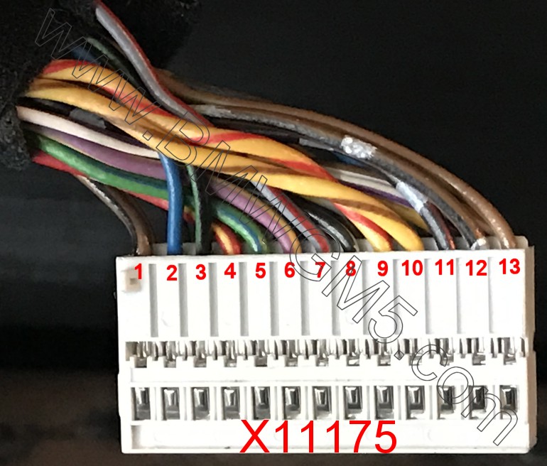
- If you want your older cluster to have backlight in an MS45 car you need to run a wire from Pin 47 (Grey with Red Stripe) of the LCM to Pin 7 of the x11175 (big black connector). After running the wire you will have backlight. -> @Drummy
--
Credits: @nextelbuddy, @TerraPhantm, @drukhadze