

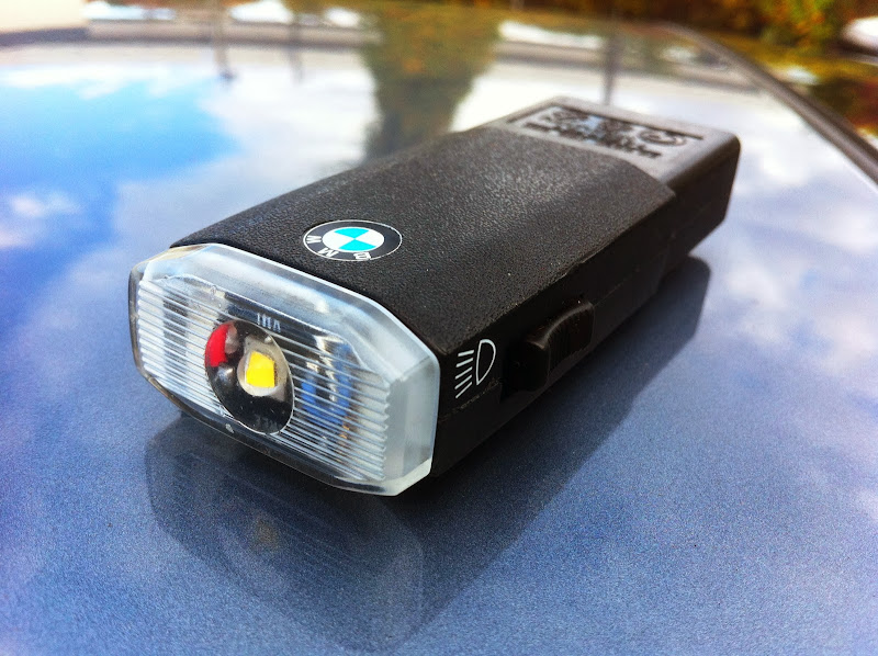
[FONT=***8220;Georgia***8221;]400 Lumens BMW Flashlight! [/FONT]
![Image]()
[FONT=***8220;Georgia***8221;]Goal:[/FONT]
Completely change your stock BMW flashlight to be significantly brighter (high power LED instead of incandescent) and last a lot longer (lithium ion batteries instead of NiCd or NiMH) while keeping the OEM look and operation.
[FONT=***8220;Georgia***8221;]Results to Expect:[/FONT]
The total power will be 5.7x greater (.72 watts to 4.1 watts). The battery capacity (not to be confused with runtime) will be over 5x greater (250 mAh to at least 1360 mAh). The light output will be 67x greater (around 6 lumens to 400 lumens).
[FONT=***8220;Georgia***8221;]Flashlight Part Numbers:[/FONT]
This is for BMW part number 63316962052 (black one, older part numbers 63318377861, 63318377862, 63316962051, 63318360066). It should also work for the older white style ones (82119413237 or 82119413147-10pk) with a few modifications. It works for the rechargeable glove box flashlight in various BMW models including the 3-series (e46, e90 (pre-2008)) and 5-series (e39, e60, e61), 6-series (e63, e64), 7-series (e38, e65, e66), x5 (e53), and others (e23, e24, e28, e30, e31, e32, e34, e36) with the white one. So, many years and models up through 2007, but some specific years and trims do not have it (older ones may have to be European). If you have a rectangular BMW flashlight in your car and the charging spot in your glove box, you can do this. Mine is a manual 2001 330i, e46.
[FONT=***8220;Georgia***8221;]Overview of the connections that will be made inside the flashlight:[/FONT]
12V plugs in flashlight > 12V to 5V step-down circuit > li-ion charging circuit > batteries > switch > LED driver > CREE LED
[FONT=***8220;Georgia***8221;]Required Materials (price includes shipping, sorry for when these links inevitably break):[/FONT]
***8226; LED - $5 (CREE XM-L2 neutral white, 16mm diameter heat sink) http://www.fasttech.com/products/1609/10003889/1425001
***8226; LED driver circuit - $2 (3xAMC7135, 3 - 4.5V input, 1050ma output, 5 mode, 17mm diameter) http://www.fasttech.com/p/1124801
***8226; 12V to 5V step-down circuit - $7 (Elago Nano USB car charger) http://www.amazon.com/gp/product/B002WH3QLE
***8226; Lithium ion battery charging circuit - $6 (TP4056 chip, 4.5 - 5.5V input, 1A output) http://www.ebay.com/itm/181164645863
***8226; 2 Lithium ion batteries - $10 (3.7V, Nikon EN-EL11 / Olympus LI-60B / Pentax D-LI78 or similar) http://www.amazon.com/gp/product/B009X6XBQM
***8226; Non-conductive thermal glue - $7 (Artic Alumina Thermal Adhesive) http://www.amazon.com/gp/product/B0009IQ1BU
***8226; Tiny heat sinks - $9 (optional) http://www.amazon.com/gp/product/B007XACV8O
***8226; Electronic grade silicone adhesive - $11 (optional) http://www.amazon.com/gp/product/B004SPJN6K
***8226; Solder (for electronics)
***8226; BMW glove box flashlight - $priceless (well, actually $35 online)
![Image]()
![Image]()
[FONT=***8220;Georgia***8221;]Required Tools:[/FONT]
***8226; Soldering iron and desoldering tool/braid
***8226; Dremel or other rotary tool
***8226; Multimeter
***8226; Small knife, wire cutter and screw driver
[FONT=***8220;Georgia***8221;]Required Abilities:[/FONT]
***8226; Patience
***8226; General circuit knowledge
***8226; Steady hands
***8226; Able to solder/desolder SMDs. For example, you will have to solder this resistor:
![Image]()
[FONT=***8220;Georgia***8221;]Warnings:[/FONT]
***8226; You will be working with electricity; do not get shocked.
***8226; You will be working with very hot items; do not get burned.
***8226; You will be using a rotary tool; use glasses and gloves and do not cut into yourself.
***8226; You will be working with very bright lights; watch your eyes.
[FONT=***8220;Georgia***8221;]Step 1 - Reduce the size of all components.[/FONT]
After gathering all the materials, everything needs to be made smaller to fit into the BMW flashlight case. You will find that every half millimeter (metric because it is a BMW) that you remove makes a difference.
[FONT=***8220;Georgia***8221;]1A - Battery Charger [/FONT]
You need to cut your battery charger board smaller, but in order to make it small enough, you will need to move some SMDs (surface mount devices). In this picture, the SMDs that need moving have been removed:
![Image]()
Create new pads for the two capacitors and the two resistors near the edge, 4 total SMDs. The pads should be closer in toward the chip. To create new pads, scratch off the blue coating to get to copper, then add solder to the new pad. Use your multimeter to ensure you are creating the pads on the same copper traces. You can see the new pads next to the old ones:
![Image]()
Then, cut the board at the edges of your new pads and solder the SMDs onto their new pads on the board. Here the pads have been moved and the board has been cut. The 4 removed SMDs have not been replaced yet:
![Image]()
[FONT=***8220;Georgia***8221;]1B - 12V to 5V Step Down Circuit[/FONT]
Break open the step down circuit, it is glued shut.
Here it is broken open:
![Image]()
![Image]()
Cut off the USB connector and as much else as you can. Find out where you will connect before you cut so that you are sure it is connected to the correct location. The outer two pins of the USB carry the 5V positive and negative.
![Image]()
![Image]()
Make sure that it will fit by placing it on the top of the flashlight (with the cover and bulb removed) in this orientation:
![Image]()
[FONT=***8220;Georgia***8221;]1C - The LED and Driving Circuit[/FONT]
Use the bulb cover to determine how much you will need to remove from the LED base plate and LED driver.
LED Driver:
![Image]()
Your main cut will happen through the empty AMC7135 pad. I chose this LED driver because it had multiple modes and because it had the most number of AMC7135 chips (3) that would still allow me to cut it down to fit in the flashlight.
Make sure you know where the circuit traces run so that you know what you can and cannot cut (or repair it if you do). Note where the positive and negative output wires are connected; it will be easier to desolder them and then cut the circuit. You will end up cutting both sides of the ground (negative) ring so make the ground ring continuous with solder and wire.
![Image]()
Fit into bulb cover:
![Image]()
Cut the LED base plate. This is easier than the driver, but again make sure not to cut the two traces.
![Image]()
Here the base plate has been cut:
![Image]()
[FONT=***8220;Georgia***8221;]1D - The Case and Existing Parts[/FONT]
Open the case and carefully dremel out all the interior plastic. This will allow the larger batteries and extra circuits to fit.
The case is glued shut and can be opened by carefully prying at the joints :
![Image]()
Mark or note the location of the plug connected to the positive side of the battery and the plug connected to the negative side of the battery. You will need this information later when you are connecting the plugs to the new circuits.
Remove the green circuit attached to the two plugs at the bottom of flashlight. This will separate the plugs but the case will still hold and align them after it is assembled. The existing circuit was used to charge the old batteries, but this wasting valuable space and cannot be reused. Our new 12V step-down circuit will replace it.
Also, I removed about a millimeter of the flat top of the plugs to give myself more room in the case.
Halfway through removing the plugs from the old charging circuit:
![Image]()
The interior plastic and old charging circuit removed :
![Image]()
Recycle the old switch components so that it works with the same action as before.
Use some side cutters to remove the extra metal from the switch spring:
![Image]()
Flatten the other side of the switch (except for the tab that contacts the spring) and made the hole slightly bigger.
![Image]()
[FONT=***8220;Georgia***8221;]1E - The Batteries[/FONT]
Carefully, remove the white sticker off of the battery. Most lithium ion batteries will have a protection circuit inside a plastic casing that surrounds the cell. The metal case is the same as the positive (+) terminal of the battery, so remember to add insulation to the thin sticker later to protect other parts and circuits:
![Image]()
Then, you can remove the black plastic covering. You will then see the protection and temperature circuit. I considered removing this circuit, but in the end I decided to leave it on. The new smaller size can be seen on the right:
![Image]()
[FONT=***8220;Georgia***8221;]1F - See if it Fits![/FONT]
You can now test to make sure that it all fits inside the case.
Starting now, you will need to be careful about the battery contacts touching the various circuits. The last thing you want to do it fry one. The battery charging circuit is the most likely to get fried and it does not have any reverse polarity protection. Cover the battery with electrical tape.
Now is a good time to show you the finished layout. If you lay the parts in loosely like below and close the lid, you should have a good idea if you can make it fit. If it does not fit, keep making things smaller until it does.
![Image]()
The LED and LED driver will go outside of the flashlight case, so just make sure they fit inside the bulb cover.
DIY continues in the next post...!
[FONT=***8220;Georgia***8221;]Goal:[/FONT]
Completely change your stock BMW flashlight to be significantly brighter (high power LED instead of incandescent) and last a lot longer (lithium ion batteries instead of NiCd or NiMH) while keeping the OEM look and operation.
[FONT=***8220;Georgia***8221;]Results to Expect:[/FONT]
The total power will be 5.7x greater (.72 watts to 4.1 watts). The battery capacity (not to be confused with runtime) will be over 5x greater (250 mAh to at least 1360 mAh). The light output will be 67x greater (around 6 lumens to 400 lumens).
[FONT=***8220;Georgia***8221;]Flashlight Part Numbers:[/FONT]
This is for BMW part number 63316962052 (black one, older part numbers 63318377861, 63318377862, 63316962051, 63318360066). It should also work for the older white style ones (82119413237 or 82119413147-10pk) with a few modifications. It works for the rechargeable glove box flashlight in various BMW models including the 3-series (e46, e90 (pre-2008)) and 5-series (e39, e60, e61), 6-series (e63, e64), 7-series (e38, e65, e66), x5 (e53), and others (e23, e24, e28, e30, e31, e32, e34, e36) with the white one. So, many years and models up through 2007, but some specific years and trims do not have it (older ones may have to be European). If you have a rectangular BMW flashlight in your car and the charging spot in your glove box, you can do this. Mine is a manual 2001 330i, e46.
[FONT=***8220;Georgia***8221;]Overview of the connections that will be made inside the flashlight:[/FONT]
12V plugs in flashlight > 12V to 5V step-down circuit > li-ion charging circuit > batteries > switch > LED driver > CREE LED
[FONT=***8220;Georgia***8221;]Required Materials (price includes shipping, sorry for when these links inevitably break):[/FONT]
***8226; LED - $5 (CREE XM-L2 neutral white, 16mm diameter heat sink) http://www.fasttech.com/products/1609/10003889/1425001
***8226; LED driver circuit - $2 (3xAMC7135, 3 - 4.5V input, 1050ma output, 5 mode, 17mm diameter) http://www.fasttech.com/p/1124801
***8226; 12V to 5V step-down circuit - $7 (Elago Nano USB car charger) http://www.amazon.com/gp/product/B002WH3QLE
***8226; Lithium ion battery charging circuit - $6 (TP4056 chip, 4.5 - 5.5V input, 1A output) http://www.ebay.com/itm/181164645863
***8226; 2 Lithium ion batteries - $10 (3.7V, Nikon EN-EL11 / Olympus LI-60B / Pentax D-LI78 or similar) http://www.amazon.com/gp/product/B009X6XBQM
***8226; Non-conductive thermal glue - $7 (Artic Alumina Thermal Adhesive) http://www.amazon.com/gp/product/B0009IQ1BU
***8226; Tiny heat sinks - $9 (optional) http://www.amazon.com/gp/product/B007XACV8O
***8226; Electronic grade silicone adhesive - $11 (optional) http://www.amazon.com/gp/product/B004SPJN6K
***8226; Solder (for electronics)
***8226; BMW glove box flashlight - $priceless (well, actually $35 online)


[FONT=***8220;Georgia***8221;]Required Tools:[/FONT]
***8226; Soldering iron and desoldering tool/braid
***8226; Dremel or other rotary tool
***8226; Multimeter
***8226; Small knife, wire cutter and screw driver
[FONT=***8220;Georgia***8221;]Required Abilities:[/FONT]
***8226; Patience
***8226; General circuit knowledge
***8226; Steady hands
***8226; Able to solder/desolder SMDs. For example, you will have to solder this resistor:

[FONT=***8220;Georgia***8221;]Warnings:[/FONT]
***8226; You will be working with electricity; do not get shocked.
***8226; You will be working with very hot items; do not get burned.
***8226; You will be using a rotary tool; use glasses and gloves and do not cut into yourself.
***8226; You will be working with very bright lights; watch your eyes.
[FONT=***8220;Georgia***8221;]Step 1 - Reduce the size of all components.[/FONT]
After gathering all the materials, everything needs to be made smaller to fit into the BMW flashlight case. You will find that every half millimeter (metric because it is a BMW) that you remove makes a difference.
[FONT=***8220;Georgia***8221;]1A - Battery Charger [/FONT]
You need to cut your battery charger board smaller, but in order to make it small enough, you will need to move some SMDs (surface mount devices). In this picture, the SMDs that need moving have been removed:

Create new pads for the two capacitors and the two resistors near the edge, 4 total SMDs. The pads should be closer in toward the chip. To create new pads, scratch off the blue coating to get to copper, then add solder to the new pad. Use your multimeter to ensure you are creating the pads on the same copper traces. You can see the new pads next to the old ones:

Then, cut the board at the edges of your new pads and solder the SMDs onto their new pads on the board. Here the pads have been moved and the board has been cut. The 4 removed SMDs have not been replaced yet:

[FONT=***8220;Georgia***8221;]1B - 12V to 5V Step Down Circuit[/FONT]
Break open the step down circuit, it is glued shut.
Here it is broken open:


Cut off the USB connector and as much else as you can. Find out where you will connect before you cut so that you are sure it is connected to the correct location. The outer two pins of the USB carry the 5V positive and negative.


Make sure that it will fit by placing it on the top of the flashlight (with the cover and bulb removed) in this orientation:

[FONT=***8220;Georgia***8221;]1C - The LED and Driving Circuit[/FONT]
Use the bulb cover to determine how much you will need to remove from the LED base plate and LED driver.
LED Driver:

Your main cut will happen through the empty AMC7135 pad. I chose this LED driver because it had multiple modes and because it had the most number of AMC7135 chips (3) that would still allow me to cut it down to fit in the flashlight.
Make sure you know where the circuit traces run so that you know what you can and cannot cut (or repair it if you do). Note where the positive and negative output wires are connected; it will be easier to desolder them and then cut the circuit. You will end up cutting both sides of the ground (negative) ring so make the ground ring continuous with solder and wire.

Fit into bulb cover:

Cut the LED base plate. This is easier than the driver, but again make sure not to cut the two traces.

Here the base plate has been cut:

[FONT=***8220;Georgia***8221;]1D - The Case and Existing Parts[/FONT]
Open the case and carefully dremel out all the interior plastic. This will allow the larger batteries and extra circuits to fit.
The case is glued shut and can be opened by carefully prying at the joints :

Mark or note the location of the plug connected to the positive side of the battery and the plug connected to the negative side of the battery. You will need this information later when you are connecting the plugs to the new circuits.
Remove the green circuit attached to the two plugs at the bottom of flashlight. This will separate the plugs but the case will still hold and align them after it is assembled. The existing circuit was used to charge the old batteries, but this wasting valuable space and cannot be reused. Our new 12V step-down circuit will replace it.
Also, I removed about a millimeter of the flat top of the plugs to give myself more room in the case.
Halfway through removing the plugs from the old charging circuit:

The interior plastic and old charging circuit removed :

Recycle the old switch components so that it works with the same action as before.
Use some side cutters to remove the extra metal from the switch spring:

Flatten the other side of the switch (except for the tab that contacts the spring) and made the hole slightly bigger.

[FONT=***8220;Georgia***8221;]1E - The Batteries[/FONT]
Carefully, remove the white sticker off of the battery. Most lithium ion batteries will have a protection circuit inside a plastic casing that surrounds the cell. The metal case is the same as the positive (+) terminal of the battery, so remember to add insulation to the thin sticker later to protect other parts and circuits:

Then, you can remove the black plastic covering. You will then see the protection and temperature circuit. I considered removing this circuit, but in the end I decided to leave it on. The new smaller size can be seen on the right:

[FONT=***8220;Georgia***8221;]1F - See if it Fits![/FONT]
You can now test to make sure that it all fits inside the case.
Starting now, you will need to be careful about the battery contacts touching the various circuits. The last thing you want to do it fry one. The battery charging circuit is the most likely to get fried and it does not have any reverse polarity protection. Cover the battery with electrical tape.
Now is a good time to show you the finished layout. If you lay the parts in loosely like below and close the lid, you should have a good idea if you can make it fit. If it does not fit, keep making things smaller until it does.

The LED and LED driver will go outside of the flashlight case, so just make sure they fit inside the bulb cover.
DIY continues in the next post...!


")