Ever wanted to design a piston from scratch?
That's the fun I've been having for the past month or so, and let me tell you the M54B30 doesn't make life easy.
Probably the most important spec to look at when designing a piston for an engine is "compression height". This is the measurement from the center of the wrist pin to the crown of the piston. In the case of the M54B30, we need to do a little backwards math to find out what are limitations are in this area.
The distance from the center of the crank to the "deck" of the block is 211mm.
89.6mm crank throws the center of rod journal up 44.8mm.
The connecting rod is 135mm from center to center.
This gives you a "compression height" of 31.2mm from the center of the wrist pin to the deck of the block.
The wrist pin on all M54s (and most other BMW engines) is 22mm. This brings us to 20.2mm of space to work with above the wrist pin on our custom piston design.
So the next step is to figure out the ring package that we want to run. Normally for N/A engines, you'll see top and second rings in the 1mm - 1.2mm area. For FI, it's recommend to run a thicker top ring. So for my "nitrous engine", I've chosen a 1.5mm top ring, and 1.2mm second ring. The oil scraper ring is dependent on a number of variables in the oil system, as well as the stroke of the piston. The more stroke, the more oil there is to shear off the wall and you need somewhere to store this before it bleeds through the breather holes. Luckily, the M54B30 has a modest stroke and moderate amount of oil being cycled onto the piston wall. This means that we don't need to be on the high end of the oil scraper ring scale (5mm for big blocks for example) and can get by with a good 2.5mm ring.
So the combined ring stack is 5.2mm, giving us 15mm of space to place the ring lands. Assuming we are placing the oil ring directly on top of the wrist pin bore, this gives us 3 ring lands to specify
Top Land
Top piston ring
Middle Land
Second piston ring
Bottom Land
Oil scrapper ring
Probably the most critical as far as strength is concerned will be the top land. The more material we can place here on an F/I piston, the better. So this means we want to minimize the land size for the middle and bottom land to give as much as possible to the top land.
On advice from industry experts, I went with a middle land of 3mm, and a bottom land of 2mm. This leaves us with 10mm above the top ring. Sounds like a lot right? Well we still have to design the piston crown, and that's where we have to account for the valves.....
So recounting a bit of math:
Top Land = 10mm
Top piston ring = 1.5mm
Middle Land = 3mm
Second piston ring = 1.2mm
Bottom Land = 2mm
Oil scrapper ring = 2.5mm
Wrist pin radius = 11mm
Connecting rod length = 135mm
Crank stroke radius = 44.8mm
So we've used all of the 211mm of space with the reciprocating assembly.
Some might point out that the head gasket can be adjusted so that we can run the piston above the deck before it will hit the head. This is true, and to be honest, we can get gaskets 3.5mm thick. (0.140") But when you are producing maximum cylinder pressures, do you want to run that pressure against more gasket surface area or a solid cylinder bore? Most top level engine builders when not constrained by deck-height rules, will chose to run the thinnest head gasket possible. So in this case, the piston design will respect a 0.030" head gasket.
If you want to flow lots of air through moderately sized valves, you need to hold them open a long time. The peak lift value isn't as important as the average lift value in cranking degrees. With the custom camshafts I have, this means that the valves are open when the piston reaches TDC at the end of the exhaust stroke and beginning of the intake stroke. With the cams "centered" in the middle of the VANOS adjustment range, this figure is around 4.5mm for both sets of valves. Retarding the exhaust camshaft will increase this value, as well as advancing the intake camshaft. In fact, it's feasible to see lift of nearly 9mm @ TDC at the far end of the VANOS adjustment range for both the intake and exhaust camshafts. This gives you 2 options for designing the valve reliefs:
1.) You mechanically lock the cam position for what you estimate will be the best cam timing position, and design the piston to clear the valves at that position.
2.) You allow the full range of VANOS adjustment, and design the piston to clear this.
A third option is to limit the VANOS range with the ECU, but then Murphy's law is bound to show up with some glitch that ruins the engine.
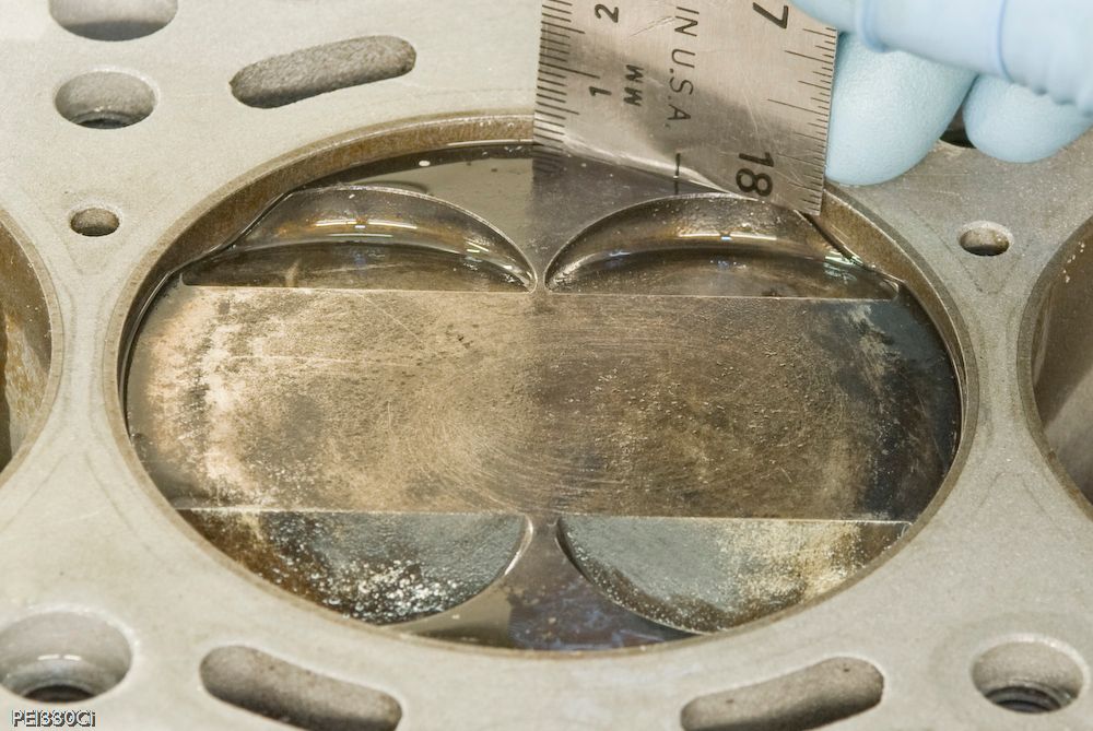
I went with option #2, and had massive valve reliefs designed into the piston crown. I reasoned that being able to manipulate exhaust cam timing was going to do more to control chamber heat than running the extra material in the crown above the top piston ring. Hopefully, with some of the other tricks I've got planned, it works.
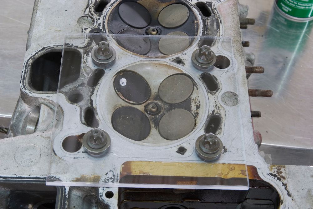
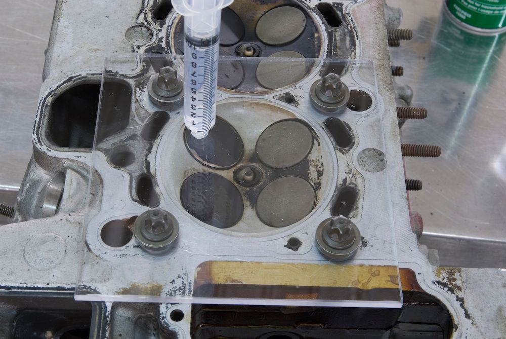
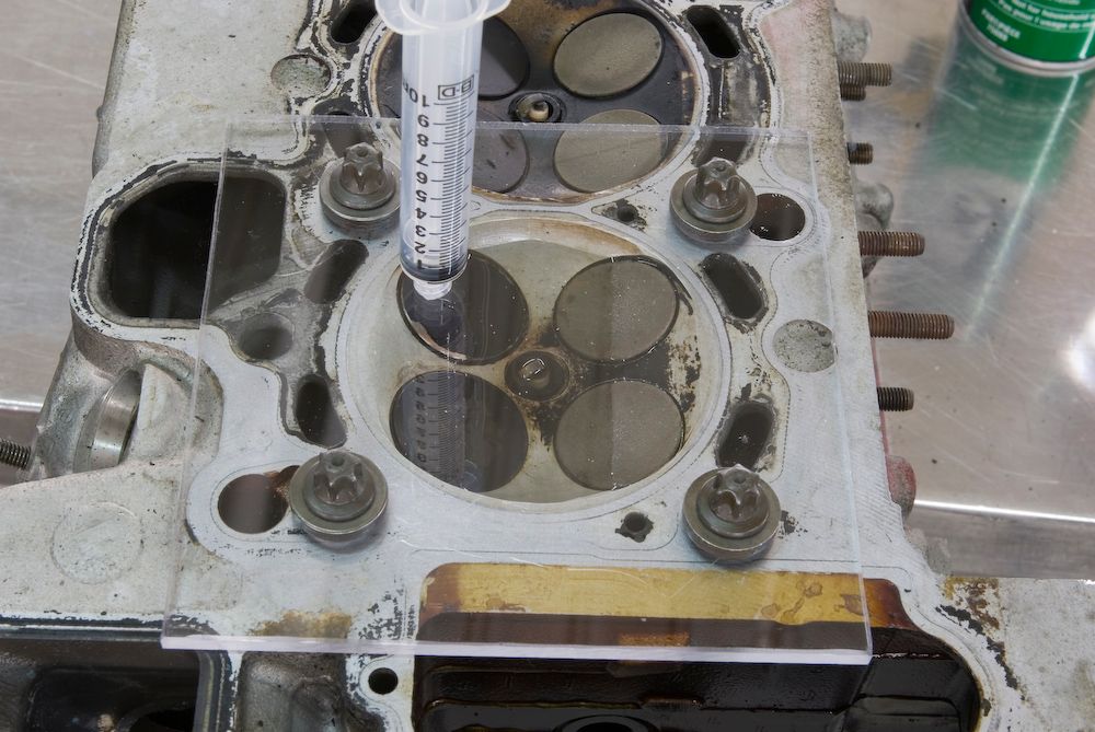
Clearance for the intake valve is 9.62mm @ TDC with a 0.030" head gasket.
Clearance for the intake valve is 8.92mm @ TDC with a 0.030" head gasket.
The result of the valve relief cuts are 2 "low" areas above the top piston ring measuring just 4mm thick across a 5mm area on the intake side, and 5mm thick across a 4mm area on the exhaust side. It's a compromise, but one that I'm willing to accept to maintain mechanically safe clearances in the event of over-reving or ECU failure.
So where does this leave the compression ratio?
11.4:1 with a 0.030" head gasket, which is actually low for nitrous race engines running race fuel.
Someone, at some point, is going to figure out what this piston design means....
")