
Engine Timing
Link to other parts of the project
http://forum.e46fanatics.com/showthread.php?t=899347
Due to the variable nature of the timing, setting it up correctly is a critical task. As many would know, this requires a number of specific BMW tools. The tools have two uses.
1. They get the timing correct.
2. They save a lot of time in the factory environment when doing the timing.
Some of the tools you don't need. Most you do, but they can be easily made if you are half handy in your workshop. I'm in the process of finalising my versions of the tools required, and I'll put them up here when I'm done.
The tools you see here are just the early versions I made up, and look pretty rough. Please don't be concerned about this. The parts of the tools that are touching the engine are actually very accurate.
Before looking at the pieces, here is a bit of an explanation of how the system works.
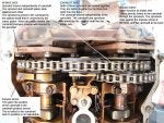
Each vanos piston is connected to a shaft that has helical splines (grooves) on both the inside and outside. The outside splines are connected to the sprockets (the gears that run on the chains that get turned by the engine). The inner splines are connected to the camshaft. Hence when the shaft is moved in or out by the vanos piston, the relative position of the camshaft and the sprocket changes. Hence variable timing.
Each camshaft has an impulse wheel. This is what is sensed by the camshaft position sensor, and tells the car's computer (DME) the position of that camshaft. If the position sensed is different to what is desired, the DME sends a signal to change the vanos piston, and consequently the camshaft position.
When looking at the gears and chains, there are numerous components, and it can all look a bit daunting. Putting it on wrong is quite difficult. It just won't fit. When everything is in the right order, it all just slides together. When I initially started to pull all this apart, my heart was really beating. It looked that complicated, and this was on an engine that wasn't in a car that I planned to drive tomorrow. If it was on my car at home I would have been sh----ing myself. Having now pulled it all apart, I don't know what all the fuss was about. It's actually pretty simple. That being said, it's a work of art. Some seriously clever engineering in here.
Some of the components are designed to be locked together and stay that way. Others are designed to slide against each other to allow for the variable mechanism. The nuts and springs (they don't look like a normal spring, but that's what they do) are there just to apply the correct pressure between the different plates to allow for the variable movement. They have nothing to do with the timing setup. The only thing you are doing when setting up the timing is getting three components on the exhaust side in the correct place, and then bolting them hard together with the small torx bolts that you see on the exhaust side.
How these three components get to the correct place is a bit complicated, and is why the tools are required. Hopefully the photos will show what I'm talking about.
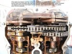
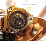
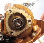
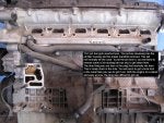
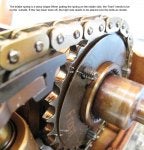
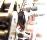
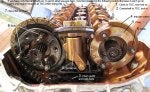
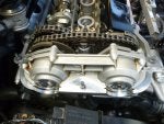
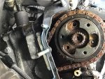
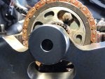
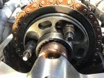
Initially, here's a couple of photos with the vanos fitted that show what is going on when things move with the variable mechanism.
![Image]()
![Image]()
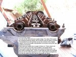
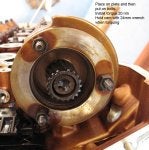
Before starting on how to do the timing, if you have re-installed the camshafts, or moved them significantly, you should not have had the engine at TDC. It should have been moved to about 30 degrees from TDC to stop any valve piston interference. Before moving the crankshaft to TDC, ensure that the camshafts are moved to the TDC position using the rear tool.
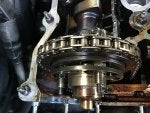
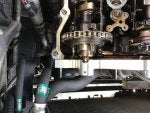
The first part of the timing is getting the camshafts in the correct position down the back.
![Image]()
![Image]()
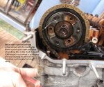
If you had removed the main sprocket or the intake impulse sensor, here are some photos that will help with their installation. Note these photos are with the camshafts in the TDC position
![Image]()
![Image]()
![Image]()
![Image]()
Be aware that getting all this on needs to be done in the correct order otherwise it won't work.
![Image]()
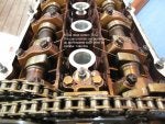
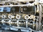
Now you need to get the engine at top dead center (TDC). You do this by turning the crankshaft at the vibration damper at the front until you see the following. At the same time, you need to look at the camshaft lobes for cylinder 1, and make sure they are in the position shown. As most know, the crankshaft goes around twice for each turn of the camshafts. So it is possible to have the two notches in the correct place on the vibration damper, but the camshafts 180 degrees out. Just turn the crankshaft another full turn if this is the case.
![Image]()
![Image]()
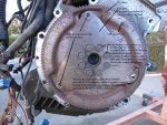
When at TDC, your TDC locking tool should fit in the position shown down the back of the engine into the flywheel. Look at the flywheel photo, and it will show you what it is fitting into.
![Image]()
![Image]()
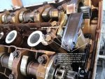
Now lets look at what is up the front when everything is pulled off. I've laid everything out here in the order that it's going to go on. When pulling it all apart, be careful. You do not want to drop something down in the head. You may not be able to get it back.
![Image]()
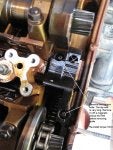
When you put everything on, the tools then go on. These are the early versions so don't take too much notice, but the picture and notes hopefully get across what is happening.
![Image]()
When putting the springs on each side, they have to go on the correct way. They should have front marked on them, but if this is worn off, here are some photos that will help.
![Image]()
![Image]()
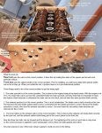
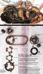
This photo has the directions on how to put it together, and then do the timing. It's important to put things on in the correct order, and when doing the timing, do it in the correct order. Otherwise it won't work. If you understand what is going on, it should be pretty obvious that it's not working when you do it wrong.
The bentley manual talks about initially torquing the torx bolts to 5nm, and then turning back ½ a turn. This has the torx nuts quite loose. Initially applying 5nm sets everything against each other correctly, but backing them off then allows them to be loose so they can be rotated to the correct position later on. The manual also talks about compressing the springs and then putting on the nuts prior to pushing on the front tool. The problem with this is that the amount of force that is required to push the shafts into the correct position when you put on the front tool is huge. Just have the smallest bit of spring pressure applied. If you have it correct, you won't be able to easily pull or push each splined shaft, but when you put on the front tool, they should be pushed in easily enough as you tighten it to the head. Make sure you have lots of oil applied to the splined shafts. I found this made a lot of difference to how hard it was to push the shafts in with the front tool. Once everything has been tightened (torx bolts 20nm, nuts 10nm), remove the rear tool and flywheel locking tool. Turn the crankshaft over twice so it gets back to TDC, with the camshafts at TDC. Put the flywheel locking tool back in, and then place back on the rear tool. The exhaust side of the rear tool should be perfectly flush with the head. The intake side should be perfectly flush, but is able to have a gap of up to 1mm on the far right hand side.
![Image]()
Some extra photos of the secondary chain tensioner and guide.
![Image]()
![Image]()
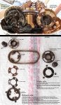
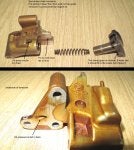
Finally, I read on a forum somewhere that someone had allowed their secondary chain tensioner to spring apart, and then couldn't get it back together again. I don't know why this would happen. Here are some photos of it pulled apart. It's very simple to put it back together. Like the main chain tensioner, it also is filled with engine oil pressure, so additional pressure on top of the spring is applied when the engine is running.
![Image]()
Link to other parts of the project
http://forum.e46fanatics.com/showthread.php?t=899347
Due to the variable nature of the timing, setting it up correctly is a critical task. As many would know, this requires a number of specific BMW tools. The tools have two uses.
1. They get the timing correct.
2. They save a lot of time in the factory environment when doing the timing.
Some of the tools you don't need. Most you do, but they can be easily made if you are half handy in your workshop. I'm in the process of finalising my versions of the tools required, and I'll put them up here when I'm done.
The tools you see here are just the early versions I made up, and look pretty rough. Please don't be concerned about this. The parts of the tools that are touching the engine are actually very accurate.
Before looking at the pieces, here is a bit of an explanation of how the system works.
Each vanos piston is connected to a shaft that has helical splines (grooves) on both the inside and outside. The outside splines are connected to the sprockets (the gears that run on the chains that get turned by the engine). The inner splines are connected to the camshaft. Hence when the shaft is moved in or out by the vanos piston, the relative position of the camshaft and the sprocket changes. Hence variable timing.
Each camshaft has an impulse wheel. This is what is sensed by the camshaft position sensor, and tells the car's computer (DME) the position of that camshaft. If the position sensed is different to what is desired, the DME sends a signal to change the vanos piston, and consequently the camshaft position.
When looking at the gears and chains, there are numerous components, and it can all look a bit daunting. Putting it on wrong is quite difficult. It just won't fit. When everything is in the right order, it all just slides together. When I initially started to pull all this apart, my heart was really beating. It looked that complicated, and this was on an engine that wasn't in a car that I planned to drive tomorrow. If it was on my car at home I would have been sh----ing myself. Having now pulled it all apart, I don't know what all the fuss was about. It's actually pretty simple. That being said, it's a work of art. Some seriously clever engineering in here.
Some of the components are designed to be locked together and stay that way. Others are designed to slide against each other to allow for the variable mechanism. The nuts and springs (they don't look like a normal spring, but that's what they do) are there just to apply the correct pressure between the different plates to allow for the variable movement. They have nothing to do with the timing setup. The only thing you are doing when setting up the timing is getting three components on the exhaust side in the correct place, and then bolting them hard together with the small torx bolts that you see on the exhaust side.
How these three components get to the correct place is a bit complicated, and is why the tools are required. Hopefully the photos will show what I'm talking about.
Initially, here's a couple of photos with the vanos fitted that show what is going on when things move with the variable mechanism.
Before starting on how to do the timing, if you have re-installed the camshafts, or moved them significantly, you should not have had the engine at TDC. It should have been moved to about 30 degrees from TDC to stop any valve piston interference. Before moving the crankshaft to TDC, ensure that the camshafts are moved to the TDC position using the rear tool.
The first part of the timing is getting the camshafts in the correct position down the back.
If you had removed the main sprocket or the intake impulse sensor, here are some photos that will help with their installation. Note these photos are with the camshafts in the TDC position
Be aware that getting all this on needs to be done in the correct order otherwise it won't work.
Now you need to get the engine at top dead center (TDC). You do this by turning the crankshaft at the vibration damper at the front until you see the following. At the same time, you need to look at the camshaft lobes for cylinder 1, and make sure they are in the position shown. As most know, the crankshaft goes around twice for each turn of the camshafts. So it is possible to have the two notches in the correct place on the vibration damper, but the camshafts 180 degrees out. Just turn the crankshaft another full turn if this is the case.
When at TDC, your TDC locking tool should fit in the position shown down the back of the engine into the flywheel. Look at the flywheel photo, and it will show you what it is fitting into.
Now lets look at what is up the front when everything is pulled off. I've laid everything out here in the order that it's going to go on. When pulling it all apart, be careful. You do not want to drop something down in the head. You may not be able to get it back.
When you put everything on, the tools then go on. These are the early versions so don't take too much notice, but the picture and notes hopefully get across what is happening.
When putting the springs on each side, they have to go on the correct way. They should have front marked on them, but if this is worn off, here are some photos that will help.
This photo has the directions on how to put it together, and then do the timing. It's important to put things on in the correct order, and when doing the timing, do it in the correct order. Otherwise it won't work. If you understand what is going on, it should be pretty obvious that it's not working when you do it wrong.
The bentley manual talks about initially torquing the torx bolts to 5nm, and then turning back ½ a turn. This has the torx nuts quite loose. Initially applying 5nm sets everything against each other correctly, but backing them off then allows them to be loose so they can be rotated to the correct position later on. The manual also talks about compressing the springs and then putting on the nuts prior to pushing on the front tool. The problem with this is that the amount of force that is required to push the shafts into the correct position when you put on the front tool is huge. Just have the smallest bit of spring pressure applied. If you have it correct, you won't be able to easily pull or push each splined shaft, but when you put on the front tool, they should be pushed in easily enough as you tighten it to the head. Make sure you have lots of oil applied to the splined shafts. I found this made a lot of difference to how hard it was to push the shafts in with the front tool. Once everything has been tightened (torx bolts 20nm, nuts 10nm), remove the rear tool and flywheel locking tool. Turn the crankshaft over twice so it gets back to TDC, with the camshafts at TDC. Put the flywheel locking tool back in, and then place back on the rear tool. The exhaust side of the rear tool should be perfectly flush with the head. The intake side should be perfectly flush, but is able to have a gap of up to 1mm on the far right hand side.
Some extra photos of the secondary chain tensioner and guide.
Finally, I read on a forum somewhere that someone had allowed their secondary chain tensioner to spring apart, and then couldn't get it back together again. I don't know why this would happen. Here are some photos of it pulled apart. It's very simple to put it back together. Like the main chain tensioner, it also is filled with engine oil pressure, so additional pressure on top of the spring is applied when the engine is running.