E46 Fanatics Forum banner
Status
Not open for further replies.

323Ci (M52tuB25) to M54B30 Complete Conversion, with MS43.0 DME and Drive By Wire

1 reading
128K views 74 replies 22 participants last post by  Victor330  
#1 ·
As I mentioned in my header build thread,

http://forum.e46fanatics.com/showthread.php?t=829844&highlight=

a buddy of mine was DD'ing. Long story short, I egged him on to drive the car hard and he money-shifted it. Based on gear ratios and engine speed when he shifted, I calculated 8500 RPM. I suspect a bent valve, causing rough idle, but won't know until I tear the M52tuB25 down.

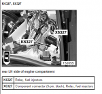
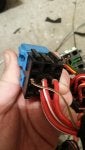
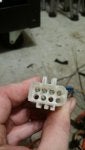
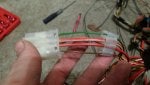
So, I purchased a 100,000 mile M54B30 from a local guy, complete with MS43.0 DME, EWS, key, and tumbler. I am just about to drop the 3.0 liter in the car. I only have 1 week to do it (Christmas shutdown at work), and spent 13 hours on Monday pulling the engine and transmission (what a BEAR!). The last 2 days have been spent researching the drive by wire conversion and swapping the old parts (accessories, oil pan with baffle, headers, etc.) and installing new parts (water pump, coolant hoses, valve cover gasket, Vanos seals, etc.). I had to visit a junkyard to get the harness connector for the new throttle pedal and to get the pins on the DME side so that I can wire in the new pedal. More on the conversion later, it is very late and I need some sleep.

Here are some pictures of me pulling the engine. I had to remove the front bumper and core support to facilitate removing the engine and transmission as one assembly through the front of the car.

Image


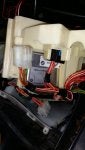
I also removed the intake so I could easily get the straps onto the rear engine hook without having the strap wrap over the intake and put stress on it.

Image


I also removed the exhaust and driveshaft, pulled the shift knob off, and popped off the rear bushing on the shifter assembly, allowing me to pull the whole shift assembly with the transmission. I then disconnected all wires that went to the chassis and pulled the whole harness with the engine. I also had to remove the right side engine mount bracket, and the left side rubber engine mount to allow for clearance between the front frame rails.

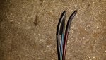
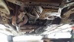
Here's a picture of the exhaust and secondary pipes/collectors still on the car. It has held up very well, especially since the exhaust and headers have been through 2 track days and 45,000 miles.

Image


As you can see, there's a pretty bad oil leak, which I later found to be a combination of the oil pan gasket, rear main seal, and oil filter housing. I guess its a good thing I'm replacing the engine now, as these problems would be a pain to do in the car (well some of them aren't hard to fix, but whatever).

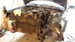
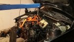
Engine coming out. Yes, those are ratchet straps, yes it's ghetto, and yes I've done it a bunch of times. One of these days, one will fail, I'll drop an engine on the ground, and I'll learn my lesson. Moving on...

Image


Image


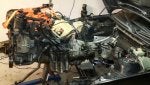
Here's a picture of the header attached to the old M52tuB25. Pretty good shape. The heat shield did its job. No problems with the valve cover gasket. Headers are not cracked or deformed, and are showing good signs given the abuse they've seen.

Image


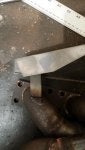
They did, however, have one problem. One of the brackets I made to mount the heat shield, which was a crappily made after-thought, cracked.

Image


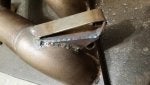
I welded it back together, and braced them all up with a triangle brace. Please excuse the crappy welds. I'm in a huge hurry to finish this project and didn't take my time to make it nice.

Image


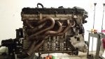
Here are the headers installed on the M54B30.

Image


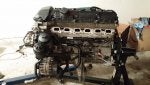
And now with the heat shield on.

Image


New coolant hard lines.

Image


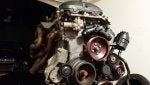
I thought this was a cool picture.

Image


I replaced a bunch of parts. Waterpump, thermostat, all new gaskets (intake, throttle body, exhaust manifold, oil pan, rear main seal, Vanos seals, valve cover gasket, oil filter housing gasket), new coolant hard and soft lines (the small ones). I also had to buy a new throttle pedal for the drive by wire, got wiring harness connectors for the new pedal from a junkyard.

Anyway, that's it for now. I plan to install the 3.0 liter tomorrow, and start working on the new DME conversion.
 

Attachments

Save
#5 ·
What will you do about the mismatch info on instrument cluster and other modules? How will you get the old asc system to be ignored by the car looking for the dsc system?
 
#6 ·
Wait, I guess since you have the coupe it may have dsc. Another question. Were your original keys the ones with the diamond shape design or the older design?
 
#7 ·
I also believe (i could be wrong) that the way the fuel delivery design was slightly different. The new system incorporated the pressure regulator into the fuel filter.... Wait. I guess you can just get another fuel filter and run a hose to where that regulator is to where it needs to go.
 
#8 · (Edited)
Here's what I've found through researching different part numbers on realoem to distinguish the differences between M52tu cars and M54 cars.

1) Drive by wire. M52tu cars are partially drive by wire, with a throttle linkage that opens the throttle and a stepper motor that can shut it. Solution: Remove old throttle peddle and cable, by new drive by wire throttle pedal. Run wires directly from the pedal to the DME.

2) Fuel system. The fuel system on an M54 car does not use a 3/2 way valve (this valve also incorporates a fuel pressure regulator), and had a fuel return from the fuel rail in addition to a return on the 3/2 way valve. Solution: remove 3/2 way valve and old fuel filter, install fuel filter from an M54 car (which has an integrated fuel pressure regulator). Also, I needed the returnless fuel rail and a new vacuum line to the fuel pressure regulator from an M54.

3) Evaporative emissions. The fuel vapor pump part number is different, and there's a note in the Bentley manual about something that's different about the fuel vapor pump on an MS43.0 DME. I haven't researched anything on this subject yet.

4) Intake (pre throttle body). Unfortunately, I had to buy a new K&N cold air intake because both the throttle body and mass airflow sensor are larger. Should be a good thing though, if the throttle body is the choke point in the flow on the M52tuB25 engine, then that I has been eliminated with the swap. I haven't personally run any flow tests on a flow bench or in CFD to verify that the throttle body is an issue, but BMW did make the throttle body larger on M54 engines, so I suspect there's good reason for it.
 
Save
#10 ·
Who wants to do it the easy way anyways? Lol. By doing it the difficult way, he then was granted our blessings to create his own thread. Anyways, I'm guessing you have the asc dsc issue figured out right? And again other than having red tamper dot in your cluster, you won't be losing too many options I don't think
 
#11 ·
I got a B30 for several reasons. Larger displacement, albeit not much over the 2.8. Larger throttle body. Tunable throttle response in the ecu (MS 43.0 that parameter can be changed, AA says that parameter is not changeable in MS 42.0). Also, I could not easily find a 2.8.

My car has DSC.

I hope my cruise control works, I don't know if it will.
 
Save
#12 · (Edited)
I got a B30 for several reasons. Larger displacement, albeit not much over the 2.8. Larger throttle body. Tunable throttle response in the ecu (MS 43.0 that parameter can be changed, AA says that parameter is not changeable in MS 42.0). Also, I could not easily find a 2.8.

My car has DSC.

I hope my cruise control works, I don't know if it will.
Hm...

Image
 
#13 ·
Interesting. Well, strike that from the list of bonus points for MS43.
 
Save
#15 ·
Well, I've finished the install and the starter cranks, but no firing. I pulled a coil and hooked a spare spark plug to it, I have spark. There is fuel pressure. In INPA, the monitors claim that the injector are firing, but hooking a bolt meter to the injector plugs show no voltage across the two injector pins (AC and DC). I have 4V on one side if the injector plug at all times, when grounded.

I have a feeling the EWS and DME are out of sync, but I don't know why they would be. They came from the same car (asking with ignition tumbler and key).

I'm stumped.

Sent from my SM-N900V using BimmerApp mobile app
 
Save
#16 ·
The engine runs! It was the fuel injector power wire. I'll post more details later.

Sent from my SM-N900V using BimmerApp mobile app
 
Save
#18 ·
Thanks! Your should check out my header build thread in the driveline, engine, and dme tuning section.

I have a couple bugs to work out. Looks like I got the O2 sensors backwards. A 50/50 shot and I seem to always reverse them.

Also, the exhaust cam position sensor on this new engine is intermittently malfunctioning. Not too bad to fix.

The car feels faster already. Considering I made 193 RWHP on the M52tuB25, I can't wait to get a tune and post the dyno results.

Also, I am already thinking cams ;-)
 
Save
#20 ·
I most likely would've grabbed a 2.8 if I could've found one local. I looked for 2 years and only found 1, which had a blown head gasket.

Either way, it is nice to have the MS43.0. I'm a fan of the larger throttle body, my theory is that the M52tu throttle body choked on my M52tuB25 at 6,000 RPM since mass flow stopped rising with engine speed. We will see if that's the case here.

I need to schedule a dyno date!
 
Save
#22 ·
Engine Installation and Wiring

Alright, guys, I'm a little behind here, but here's some pics of the engine installation. Then, I'll follow with the necessary mods to swap to the new ECU and engine, especially the wiring I did.

Dropping the engine back in was as easy as getting it out. While the engine was out, I replaced the transmission tunnel sound insulation. It was torn to shreds a few years back when the chinese guibo joint I bought exploded on the freeway.

Image


Anyway, I recruited my better half to help drop the engine back in since all my car-guy friends were with family during christmas :loco: WHY NOT WORK ON A CAR CHRISTMAS DAY????!!!

She's a trooper, wrenching on the car with me on Christmas day.

Image


I dropped the engine in through the front, just as I took it out. Did it in the parking lot this time. This apartment complex is pretty cool about this stuff :)

Image


Also, since there aren't any catalysts on the car anymore, I finally removed the secondary air pump and made a blockoff plate out of 1/8" aluminum. I'm annoyed that the studs are different heights. I used a little Permatex copper RTV to coat the gasket, this stuff works really well on exhaust parts. I also used it on all the exhaust gaskets and v-bands. Track tested, mother approved.

Image


List of new parts, just for maintenance:

(1) Rebuild Vanos seals
(2) Rear main seal - engine
(3) Valve cover gasket
(4) Motor mounts
(5) Transmission mounts
(6) Water pump
(7) Thermostat
(8) Intake and throttle body gaskets
(9) Fuel injector o-rings
(10) Dip stick o-ring
(11) Power steering reservoir o-ring
(12) Power steering pressure line o-ring
(13) New coolant hard lines on block, and the rubber hoses that attach to them
(14) New exhaust gaskets
(15) New oil pan gasket
(16) New electrical box for the ECU (the old one broke when one of the metal nut-serts seized to the screw, and was spinning instead of loosening). Surprisingly not that hard to replace the ECU box... just pull all the electronics out and disconnect all the wires:

Image


Then pull the wires through the box (after disconnecting the fasteners in the driver's side foot area, against the firewall):

Image


And install the new box:

Image


(17) Oil filter housing gasket
(18) Timing gear cover gasket
(19) Oil pickup tube gasket
(20) Oil filter housing cap o-rings (at bottom of oil filter housing cap)
(21) Shift knob (I got the performance shift knob 25110429267 since it was only an extra $20). The old one was worn through.

Image


----------------------------

Here's a list of parts that were needed to make the swap from MS42.0 to MS43.0.

(1) DME
(2) Key, all locks, ignition tumbler
(3) EWS
*Above 3 must come from the same car
(4) Fuel pressure regulator / fuel filter P/N 13327512019. The old 3/2 way valve and old fuel filter gets replaced by the new fuel filter with integrated pressure regulator.

Old 3/2 way valve (sorry for the out of focus picture):

Image


New fuel filter / fuel pressure regulator:

Image


I bought some fuel injector fuel line. The inlet and return lines needed resized because the return hard line is longer on the 323/328 due to the 3/2 way valve. I just replaced the rubber hose that goes from the hard line to the fuel filter with a longer one, then replaced the return line rubber hose as well.

(5) Vacuum line that runs from throttle body elbow to fuel pressure regulator P/N 13327561060. This can be seen in the picture above. It is the vacuum hard line that runs to the fuel pressure regulator on the fuel filter. Below is where it mounts to the F-adapter on the intake tube:

Image


(6) "Sucking jet pump" P/N 11617545382. Weird name. It is a valve that connects between the intake plenum, the brake booster, and the throttle body elbow.

Image


(7) Accelerator pedal P/N 35426786282. Wires need run to this part. Also, this will need the throttle pedal adapter plate, listed below.

Image


(8) Accelerator pedal adapter plate P/N 35426772703. Remove the old drive by cable gas pedal, take the throttle stop nut out, and install this thing with an M8 screw. Then, the accelerator pedal snaps right onto it.

Image


(9) Air intake. I got a new K&N Cold air intake, P/N 57-1001, to replace the one I had. I liked the old one, so I got a new one that fit the new mass airflow sensor.

Image


(10) Air duct P/N 13717501988. The new air duct is larger on the 330, and it has a different connection to the air box on the new cold air intake.

Image


Here, you can see the old air duct (with missing flex tube)

Image


And here is the opening in the air box that is different (323/328 is rectangular)

Image


(11) Other parts that I got with the engine, for which I don't have part numbers, too lazy to go get them: mass airflow sensor (its larger), intake manifold (it has shorter runners and a larger throttle body), throttle body (different drive by wire mechanism - there is no longer a cable that runs to it [which both serves as a mechanical backup and actuates the pedal position sensor]), fuel rail (returnless fuel rail), fuel injectors (purple top), engine wiring harness, coil harness (not sure if this is different or not, but it came with the new motor, so I used it), starter (only because it was newer and my old one had a partially stripped thread).

(12) Parts I swapped over: Headers, oil pan (I had already welded in a VAC oil pan baffle on my old oil pan. They are the same part number so I just swapped my old one after cleaning it), flywheel (I have a lightweight flywheel. The clutch is different between 323 and 330, so if you don't already have a lightweight flywheel, buying a new 330 clutch is recommended since it is larger), all accessories (i confirmed they were working so why not), lightweight pulleys, O2 sensor harness (only because it didn't come with the new motor, but they are the same).

---------------

Wiring.

There are 12 wires that need run.

(1) 6 for the throttle pedal
(2) 1 for the fuel injector power wire
(3) 2 for the EWS / starter
(4) 3 for warning lights. I haven't done this yet.

Let's start with the throttle pedal. I found a few E46 325s at a salvage yard and was able to get ALL the connectors I needed for like $20, which was super helpful, since they came with the correct color wires. Additionally, BMW connectors are really easy to depin, further making this swap very nice.

First, the diagram:

Image


As you can see, 6 wires go directly from the pedal to the DME. There are 2 potentiometers (they are a redundant system), so 3 wires per potentiometer.

The 6 pins interface with the 40 pin connector X60004 on the DME, which is grey, and looks like this:

Image


Pin 1 Pedal position sensor ----> Pin 7 X60004 DME (Brown / Green stripe)
Pin 2 Pedal position sensor ----> Pin 12 X60004 DME (Brown)
Pin 3 Pedal position sensor ----> Pin 14 X60004 DME (Yellow / Green stripe)
Pin 4 Pedal position sensor ----> Pin 8 X60004 DME (White)
Pin 5 Pedal position sensor ----> Pin 9 X60004 DME (Yellow)
Pin 6 Pedal position sensor ----> Pin 13 X60004 DME (White / Green stripe)

The pedal plug looks like this:

Image


Make sure you get a long enough lead.

Image


All I did was take the connector for the pedal position sensor that I cut off the junkyard car, solder wires to the end of it, and ran it up through the firewall. I ran it along the body harness.

Here's the wires running up along the body harness, over the steering column.

Image


And here are the wires running through the firewall into the electrical box:

Image


On the X60004 grey DME connector, just de-pin them from the donor connector and repin the wires into your car's connector. Then, solder them together.

NOTE: I did some research on soldered connections, just in case anyone is wondering. I found that a typical soldered connection has about 30-70 microOhms of resistance, where the pedal position sensor operates in the 10 ohm range, IIRC. So, the extra resistance added by the soldered connections are ORDERS of magnitude smaller than the resistance of the potentiometer. So no worries about soldering the connections.

Once its finished, it should look like this:

Image
 

Attachments

  • Like
Reactions: Jayster0966
Save
#23 · (Edited)
Wiring

Alright, onto the fuel injector power wire. There is only 1 wire that needs run, this one gave me HUGE issues since I hadn't found it on any other swap thread, and I thought it was a DME/EWS issue. I never checked the wiring diagram on this specific issue until after I went through a couple days of diagnostics. First, I got INPA working on my new laptop, which for anyone who has done that, knows it is a HUGE PITA. Then, I had to configure my Galleto 1260, by soldering 2 pins together and then running the adapter to the ADS port, which allowed me to talk to the other systems on the car. Then, I synced the DME/EWS. Then, I watched the live data to see that the injectors were being told to fire by the DME, which left only 1 thing: wiring. Either they aren't either receiving a signal, or they don't have power. It was the power wire.

Here's the diagram for the new injector harness, which I got with the new engine:

Image


The circled item is the injector power wire. The DME switches the injector signal on the ground side. Essentially, a single power wire needs run to port 87 on the fuel injector relay. On the 323/328, there is an extra port 87 open on the relay, so you only need to retrieve the correct wire from a donor car, de-pin it, and re-pin it into the relay's connector, X6327. This then runs to a white 8-pin connector X6053.

Starting with the injector relay, K6327, and connector X6327:

Image


I pulled this connector from a junkyard car and removed the center pin, which goes to port 87 on the relay (pin 5), red wire with white tracer. Picture below is the one from the junkyard.

Image


Note that there are 2 port 87s on this relay, so I used the empty one on the 323/328.

Image

Image


Depin using a 2 prong depin tool:

Image

Image


Then pin this wire into your car's X6327 connector, pin 5:

Image


This wire then runs to pin 7 on the X6053 connector (white 8 pin connector):

Image


Image


I de-pinned pin 7 on the donor connector and re-pinned it into mine, since it was an empty pin on the 323/328.

Image

Image


Then, pin into pin 7 on X6053 connector your car.

Image


Then, just solder the two wires together, make it look OEM as best you can!

Image


Alright, the last one I have today is the 8 pin X6011 black connector. On MS42 equipped cars, X6011 is a 2 pin connector, where pin 1 goes to the starter, and pin 2 is the oil level sensor (whose signal is sent to the gauge cluster).

Image


On MS43 equiped cars, the pinout is as follows. I just tested continuity on all the wires of the engine harness to get these (probably a time consuming approach - don't repeat):

(1) Starter
(2) Oil level sensor and alternator
(3) Oil pressure sensor
(4) Alternator
(5) Oil level sensor
(6) Starter
(7) Not used on manual transmission cars.

Image


For now, I just wired in pins 1 and 2. You'll need the female side of the 8 pin X6011 from a donor car, I just got mine from a junkyard.

Here's the location of X6011:

Image


And here's what it looks like:

Image


Here's the female side, which I cut from the donor car.

Image


Now, I had to cut my 2 pin X6011 from my car:

Image

Image


Then, solder pins 1 and 2 together (both pins 1 and 2 are the same between these connector). I just replaced the 2 pin female with the 8 pin female.

Image


If you're wondering what that red chode is hanging off the end of that connector, its the remaining 5 wires. A couple of them go to the gauge cluster and I haven't spent the time to figure that part out. So, I just heat shrunk the ends and then put a cap over the ends so the heat shrink can't come off.

Image

Image


Well, once I finished it up, it looked all factory in there. I was very satisfied.

Image


And, here's the (almost) completed swap. Just need my new air duct to the K&N intake.

Image

Image


I'll follow this reply with the vacuum routing and fuel vapor routing, since a lot of that changed between both cars and I retained my old systems.
 
Save
#24 ·
ok, talking about the fuel system, I did almost the same swap in my e39, but what I did was a motor stroke, but for the fuel system I use my M52TUB25 system, I have the pressure regulator in the injector fuel line, above the intake manifold and I use the M52TUB25 fuel filter..... you do not need to "upgrade" your fuel system....
I done this swap two years ago with no problem....

regards and nice swap
 
#34 ·
I was not sure of a few things.

1) Same fuel pressure between MS42 and MS43. I'd assume they are the same, but I wasn't in the mood to research it.

2) Operation of the 3/2 way valve with the new electronics. I didn't have a fuel pressure regulator on the fuel rail, it was at the 3/2 way valve.

Bonus is that it is much cleaner now, with the integrated fuel filter/regulator.

Thanks for pointing that out.
 
Save
#25 · (Edited)
Thanks for providing all this information for anyone that would like to do a full swap including going to MS43 and drive by wire but for anyone that is interested in an easier way, you can just swap the m54b30 in and retain your ecu by simply retaining your throttle body and adapting it onto the 330's manifold. Also you can just retain your old fuel rail. Then just tune for 330 injectors flow rate or swap 328i injectors in and adjust tune for them.
 
#26 ·
Certainly this is true. In fact, I made an adapter, as I was running a B30 intake on my M52tuB25. However, the major downfall is that the throttle body, intake tube, and mass airflow sensor are all smaller on the M52tu engines.

Sent from my SM-N900V using BimmerApp mobile app
 
Save
#29 ·
under WOT the throttle Body opens only to an angle of 81 degrees limited by dme. Some Time ago I changed that up to 90 degrees and performed air flow measurement via realtime datalogger but unfortunately without any gains on a m54b30 with schrick cams 264/248. The throttle body is not limiting the airflow....
 
#30 ·
Interesting.

Stupid question, but has anyone verified that the throttle plate is actually at 81% and not 100%?

Sent from my SM-N900V using BimmerApp mobile app
 
Save
#35 ·
I hear what you're saying, and it is a good point. The only thing I question is is there actually a difference in true throttle position (not what the DME says) between 80-100%?

In addition, there is almost the same cross-sectional flow area between those 2 points. I have some math on this, but it isn't in front of me right now. I'll have to dig through some old files and plot it up for you guys.
 
Save
#43 ·
Pics show for me.

I think the posts I've made do a good job of summarizing the swap. What else do you need to know? Maybe I missed something.
 
Save
#33 · (Edited)
Have verified on the older MS42 cable driven systems that when inpa or a logger show 80% throttle openings the throttle is actually at 100.

Hakken, the cable driven throttles are just that... with the attached motor having the ability to override the drivers commands and provide functions such as cruise control and traction control. However, the throttle operates primarily based on the mechanical cable in MS42 systems.
 
#44 · (Edited)
Based on the MS42 documents, it's the other way around. The motor overrides the cable unless a fault is detected

Also according to Tool32, the unit the MS42 and MS43 for throttle position use is degrees, not %. I don't know if the 81Âş limitation is because the "0" position is actually 9 degrees or something along those lines
 
Status
Not open for further replies.
You have insufficient privileges to reply here.